Table of Contents
AiGIS
Overview
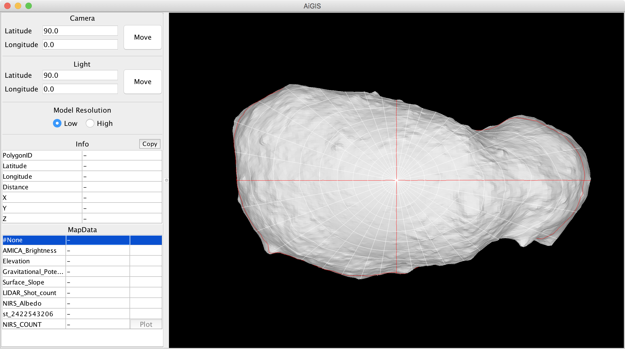
AiGIS is a 3D GIS designed for analysis on exploration data of irregular-shaped small bodies. The shape of a target body is represented by a polygon model, and geographic information is associated with polygons of the model. AiGIS can visualize and manipulate the shape model and map data on it.
Download
Latest release
- 2023/11/17版
- Mac: AiGIS_v20231117_mac.zip
- Linux: AiGIS_v20231117_linux.zip
- Windows: AiGIS_v20231117_win.zip
- JAR: AiGIS_v20231117_jar.zip
Please contact us to obtain the source code.
Release note: 2023/11/17
- Support multiple (3 or more) shape models
- Support macOS Ventura and Sonoma
Previous releases
Previous releases can be found here.
Sample data
These data are distributed as a sample. DO NOT use them in your actual scientific research projects. See below for a detailed description of the dataset for AiGIS.
Utilities
Latitude-Longitude grid generator
How to use
Start-up
- Once starting-up, AiGIS ask you the place of your data directory
- Sample data are distributed from the same place you get AiGIS
- Data directory should contain a setting file AiGIS_setting.txt
- You can edit the file if you want to add or change your dataset
- Windows user may requested to install a VC++ library to run AiGIS
Data
- AiGIS can load Shape model in Wavefront object format (.obj)
- Two different model files (low and high-res or two models to be compared) can be loaded
- If you have only a single model, you can use is as the low-res model (high-res model can be omitted). If you want to use the Multi-view mode, we recommend using a single model to avoid slowing down of operation.
- A line starting '#' is treated as comments in Shape models, Map data, and Graph map data
- See below for Map data and Graph map data formats
Model manipulation
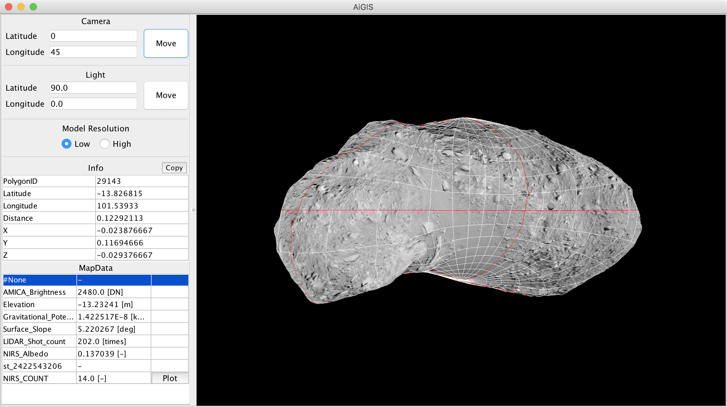
- Rotate the asteroid by mouse operation
- with Shift key to move the light source direction
- with Option key or use wheel to zoom in and out
- with Control key to translating the asteroid
- with 'X', 'Y' or 'Z' to rotate along the fixed axis (NEW)
- Asteroid rotation and light source direction can be changed by using dialog in the main window
- Uncheck “View>Shading” to turn off direct lighting
- Better to use when you view a grayscale map data
- Check “View>Fixed Light” to fix the lighting direction to the target body (NEW)
- Select “View>Reset view” to reset the view to the initial state
Work with Map data
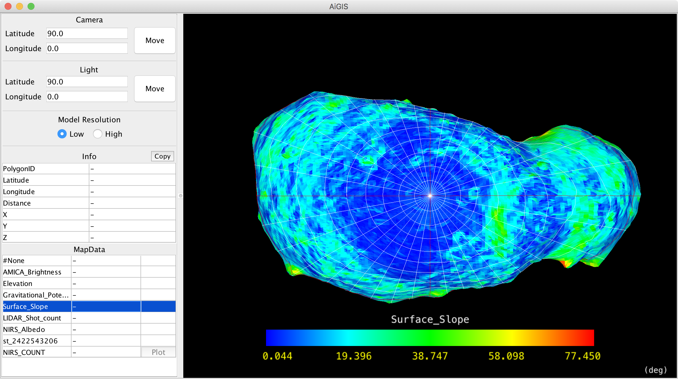
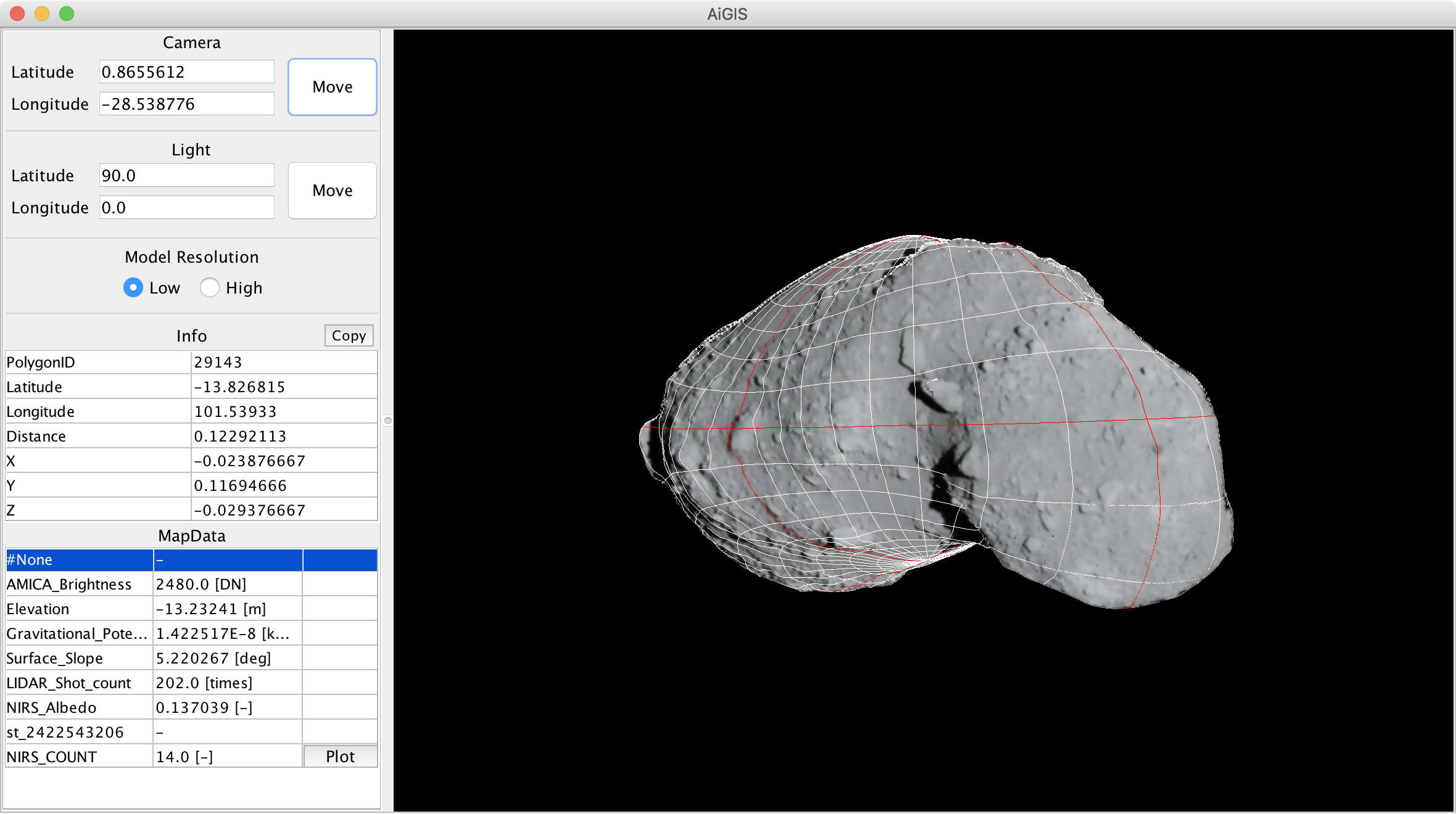
- Select a data to view in the Map data list
- Arrow keys (up/down) can be used to change the data
- Click on the model to extract values on the polygon (Clicked polygon will be colored with red)
- Values can be copied to your clipboard with the “Copy” button
- Rainbow and grayscale are available as built-in look-up-tables (LUT) for Map data
- User-defined LUTs can be imported (see below)
- Select “View>Rescale Color Range” to change LUT-Map data value assignment
- Select “MapData>Sort By Name or By FileName” to sort MapData in the list
- Select “MapData>Reload” to reload all map data in the current dataset (shape models are not reloaded)
User-defined LUTs
- Definition of a LUT should be described in the txt format appeared in Scientific colour-maps by F. Crameri
- Place your LUTs in a directory
- Path to the directory with user-defined LUTs should be defined in LookUpTablePath of the Setting dialog (“File>Settings…”)
- List of the user-defined LUTs will appeared in Look-up Table menu (“View>Look-up Table”)
Work with Graph map data
- Select a map data associated with a graph map data
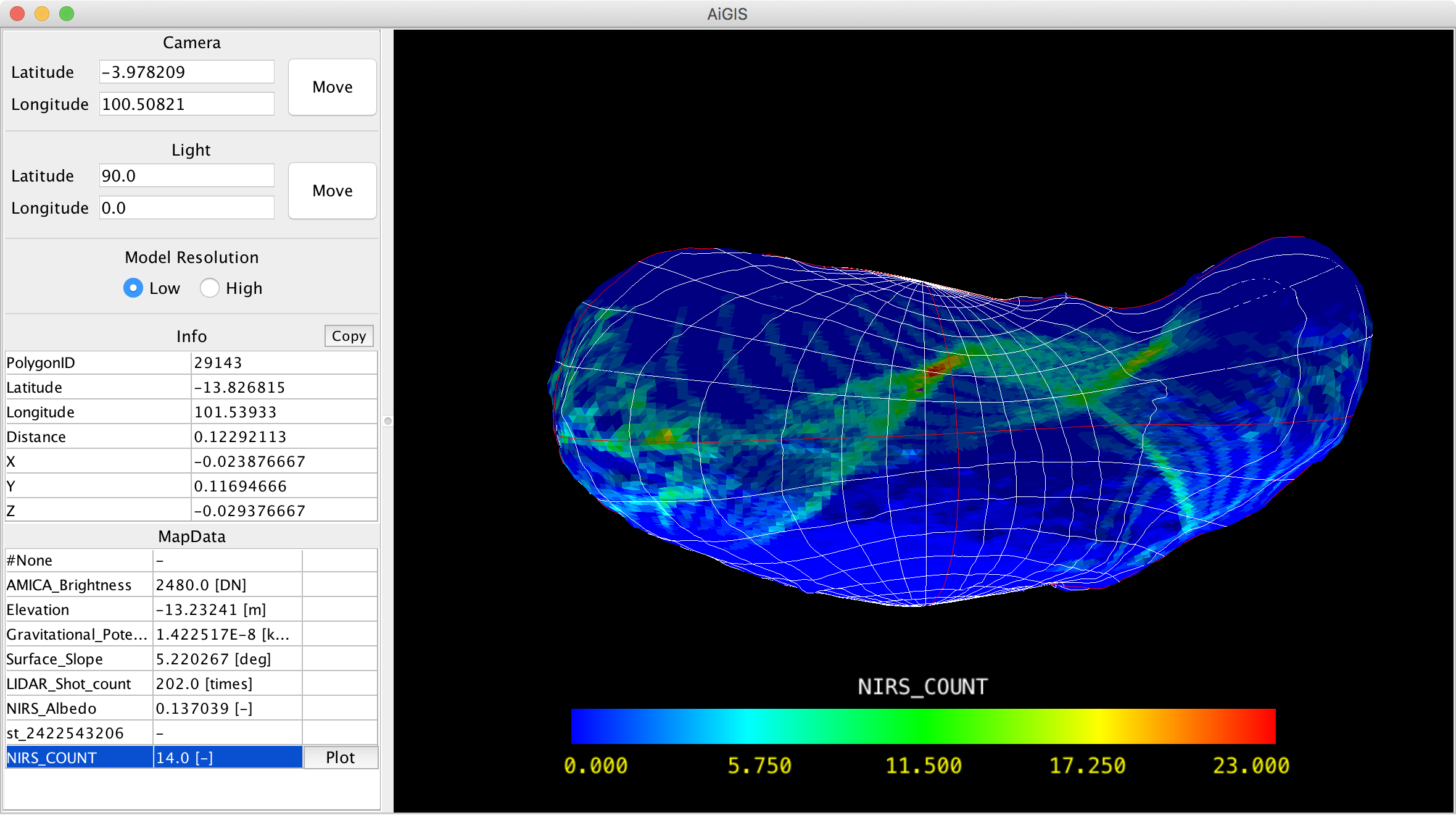
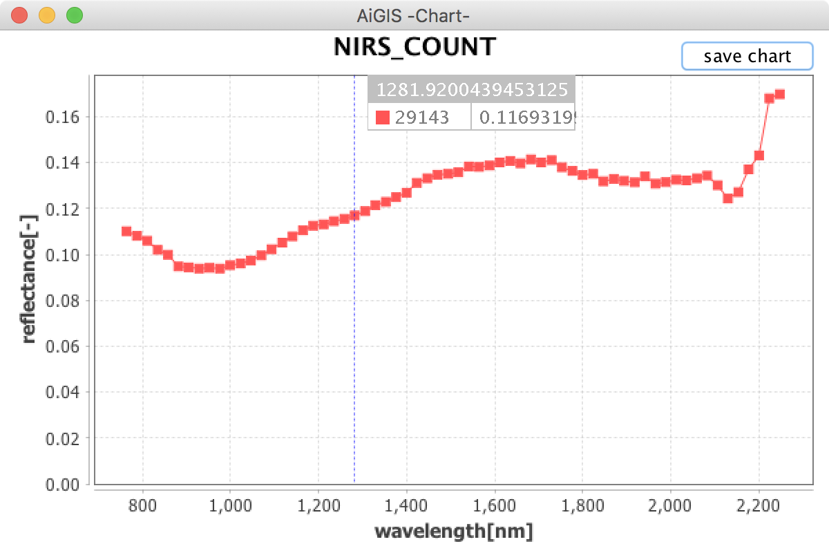
- NIRS_COUNT in the Itokawa sample data set is associated with NIRS Spectra data
- Click on the model to select the target polygon (Clicked polygon will be colored with red)
- Click “Plot” in the map data list to show the plot in a plot window
- Plots can be added to the plot window to repeat this operation
- Click “save chart” in a plot window to export plot data
Image and Map image mapping
- Choose “Image>Open Image/Map Image…” to map an image with geometry information or a map image in the simple cylindrical projection.
- Images in general image formats (jpg, png…) and FITS format can be loaded to AiGIS. NEW
(Currently a FITS image is not acceptable)
- Now you can map multiple images on the shape model
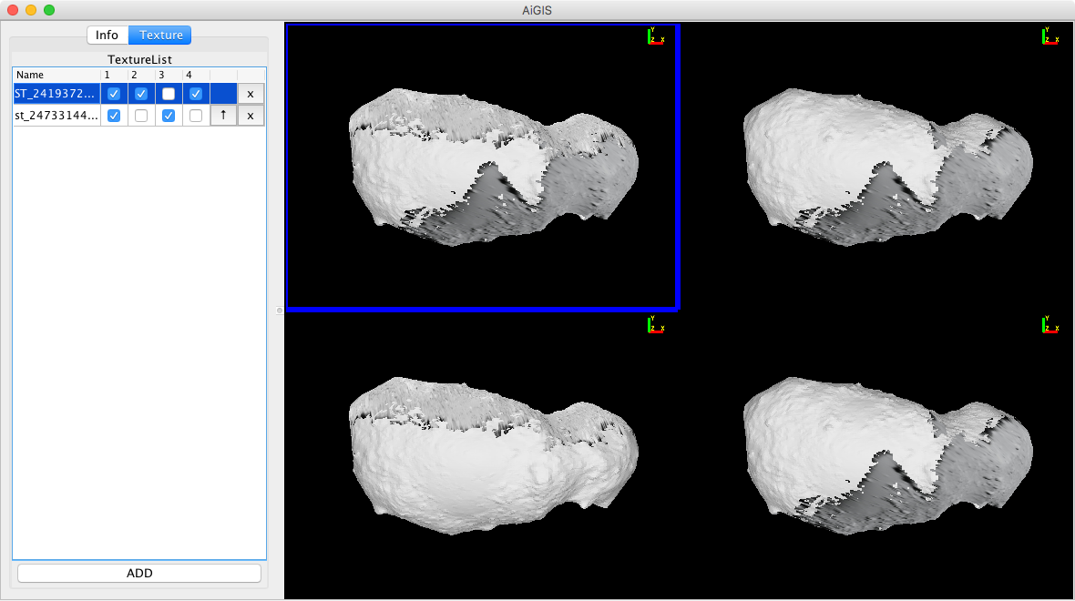
- Control on mapping order and show/hide images is available in Texture tab
- Geometry information should be provided in the INFO format used in Small Body Mapping Tool developed by APL/JHU and the SUMFILES format used in Stereophotoclinometry (SPC) software developed by R. Gaskell.
Multi-view mode
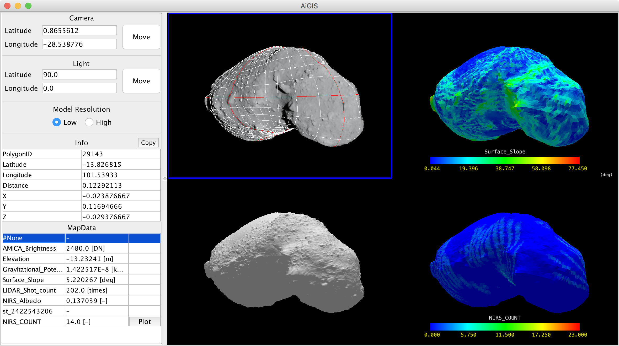
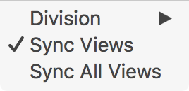
- Choose “Multi-View>Division” to enter the Multi-view mode.
- Uncheck “Sync Views” to stop synchronized operation to the models in the Multi-view mode
- Select “Sync All Views” to synchronize displays in the Multi-view mode
Setting-up
Preferences on directories for data, saved images, and saved plot data can be set in the Setting Pane at “File>Settings…” Now you don't need to edit the AiGIS preference file (AiGIS.properties).
Items in the Setting Pane
- DefaultDataPath: Path to your AiGIS data
- SavePngPath: Path to snapshot images taken in AiGIS
- SaveGraphDataPath: Path to location where plot data are exported
- LookUpTablePath: Path to user-defined LUTs
defaultImageMapPath: Path to your images and image maps dataNow default image path is defined by IMAGEMAPDIR in AiGIS_setting.txt for individual data sets- NOTE to Windows users: Path delimiters should be doubled in the setting.
- For example, your path to 'C:' should be indicated 'C:\Users\CurrentUserName\AiGISData'
Menus
File menu
- Open…: Load another data set
- Save Snapshot: Save a snapshot of the main view in png format. The location of the saved images can be changed by modifying savePngPath setting in AiGIS.properties
- Setting…: Set preferences on user data directories (NEW)
- About…: Show an About window (NEW)
View menu
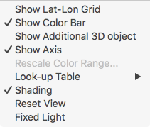
- Show Lat-Lon Grid: Show and hide the latitude-longitude grid
- Show Color Bar: Show and hide the color bar for map data
- Show Additional 3D object: Show and hide additional 3D objects
- Rescale Color Range: Change LUT-Map data value assignment
- Look-up Table: Change LUT (Rainbow, Grayscale and user-defined LUTs)
- Shading: Turn on/off direct lighting
- Reset view: Reset the view to the initial state
- Fixed Light: fix the lighting direction to the target body (NEW)
Multi-View menu
- Division: Enter the multi-view mode to choose 2 or 4, and end the mode to choose 1
- Sync Views: Uncheck to stop synchronized operation to the models in the Multi-view mode
- Sync All Views: Synchronize displays in the Multi-view mode
Image menu
- Open Image/Map Image…: Open a dialogue to choose an image with geometry information or a map image in the simple cylindrical projection to map it on the shape model
MapData menu
- Sort By Name/By FileName: Sort MapData in the list *(NEW)*
- Select “MapData>Reload” Reload all map data in the current dataset (shape models are not reloaded) *(NEW)*
Data format
Map data
Sample: Itokawa_elevation_64.txt
#Data Name (Appeared on the Map data list)
Elevation
#Unit (or description)
[m]
#The Number of Polygons
49152
#Polygon_ID Value (Tab and Space is allowed as delimiter)
1   -3.451888084411621
#Continue for all polygones
2   -3.431725025177002
3   -3.906290054321289
4   -4.018442153930664
5   -4.496425151824951
Notes on Map data
- No duplicated Data Name is allowed for map data for a model
- Hyphen '-' can be used when no value is available on a certain polygon
- A line starting '#' is treated as comments in Map data, Graph map data, and Shape models
Graph map data
Sample: nirs_spcmap_051116.txt (NIRS Spectra)
#Name of Map data that the graph map data is associated
NIRS_COUNT
#Unit (or description) for the X-axis
reflectance[-]
#Unit (or description) for the Y-axis
wavelength[nm]
#The Number of Polygons
49152
#_ Values for the X-axis (1st column should be '_') ...
_ 2247.88 2224.32 2200.76 2177.20 ...
#Polygon_ID Values for the X-axis ...
1 0.000000 0.000000 0.000000 0.000000 ...
#Continue for all polygones ...
2 0.000000 0.000000 0.000000 0.000000 ...
Notes on Graph Map data
- Lines starting '#' are treated as comments in Graph map data, Map data, and Shape models
Data set structure
Minimum contents of the data set directory for AiGIS are as follows:
- AiGIS_setting.txt
- Shapemodel directory
- MapData directory
- MapDataHigh directory
The Shapemodel directory is usually used to place shape models and gird data, but they can be placed outside this directory. Files in MapData and MapDataHigh directories are assumed and try to load as map data for the SHAPE and SHAPEHIGH models respectively.
If a data set have 3 or more shape models, these directories will be assessed to load map data for additional shape models:
- MapData1 for the SHAPE1 model
- MapData2 for the SHAPE2 model
- same for MapData3, 4, …
- MapDataHigh1 for the SHAPEHIGH1 model
- MapDataHigh2 for the SHAPEHIGH2 model
- same for MapDataHigh3, 4, …
Items in AiGIS_setting.txt
All items in AiGIS_setting.txt are described in KEY = VALUE style. Multiple VALUES may be assigned in the following format
KEY = VALUE1,VALUE2,VALUE3
- SHAPE (mandatory)
- Path to the low-resolution shape model in the relative path style from the directory placed AiGIS_setting.txt
- SHAPEHIGH (optional)
- Path to the high-resolution shape model.
- GRIDR/GRIDW (mandatory)
- Path to the latitude-longitude grid data. The same grid data will be applied both the low-resolution and high-resolution models. Because this items are mandatory, you may prepare dummy grids for shape models that grids are unavailable.
- CHANGEMODEL (optional)
- TRUE or FALSE to control automatic change of displayed model while model manipulation. The low-resolution model is displayed while model manipulation when CHANGEMODEL is TRUE even the high-resolution model is selected to be displayed.
- MAPDATA/MAPDATAHIGH (optional)
- Path to additional map data for the low-resolution model and high-resolution model not placed in MapData/MapDataHigh directories, respectively. Multiple values are accepted.
- CHARTDATA (optional)
- Path to graph map data. Error will be occurred when a graph map data doesn't have an associated map data
- GRID (optional, this keyword may be renamed in future)
- Path to directory containing data of additional 3D objects
- IMAGEMAPDIR (optional)
- Path to directory containing image data and relating geometry information files
If a data set have 3 or more shape models, the following KEYs can be used:
- SHAPE1, SHAPE2 …
- SHAPEHIGH1, SHAPEHIGH2 …
Keywords MAPDATA, MAPDATAHIGH, MAPDATADIR, MAPDATADIRHIGH and CHARTDATA can also be sequentially numbered for numbered shape models.
The numbered two models (e.g. SHAPE1 and SHAPEHIGH1) will be paired for the CHANGEMODEL function.
History
- 2023/11/17
- Support multiple (3 or more) shape models
- Support macOS Ventura and Sonoma
- 2023/01/15
- Fix bugs relating shape model handling
- 2019/11/11
- Support FITS image (including multibyte image)
- Support SUMFILEs of SPC as imaging geometry information
- Support user-defined look-up-tables (LUT)
- 2019/03/10
- Improved image mapping capability with multi-image mapping
- Quick reloading of map data
- Fixed lighting mode
- Fixed-axis rotation mode
- Reorganized preference setting feature
- 2018/07/17
- Improve multi-view mode with high-resolution shape models
- Rebuild user interfaces
- Fix several bugs
- 2018/03/15
- Initial release
Contact
Please send your questions and comments to Naru Hirata (naru@u-aizu.ac.jp) or our group mail address (arcspace@u-aizu.ac.jp).
Reference
Acknowledgements
AiGIS was originally developed as a research project by students at the University of Aizu.
The project is/was supported by:
- JSPS KAKENHI Grant Number 17K05639, “FY2017-19 Coordination Funds for Promoting AeroSpace Utilizaiton MEXT, Japan”
- ARC-Space, the University of Aizu, Distinctive Joint Research Center supported by MEXT Grant Number JPMXP0619217839/JPMXP0622717003/JPMXP0723830458.
- Collaborative research between JLPEDA/JAXA and the University of Aizu.
Aizu Laboratory, Inc. supports development and maintenance of the software.

